0x01 前言
我一直搜寻合适的温度监控硬件,要能通过网络获取数据的那种。因为工作的关系,我接触到施耐德专业的动力环境监控设备。但是这类专业的设备非常昂贵,软件还需要授权,所以这并不适合家庭使用。
在经过多方面的资料搜索,我决定自己建立一个温度监控系统。
0x02 准备
我选择以树莓派为基础,搭配数字式温度传感器,最后通过zabbix取值、分析与记录。在开始之前需要准备以下东西:
- 树莓派3 B+ 带外壳套装 x1,400元;
- DS18B20 数字温度传感器 x5,25元;
- 4.7千欧电阻 x100,1.5元;
- 面包板 x1,7元;
- 杜邦线 x1,4元;
- 网线 x10m,10元;
- 热缩管 直径4mm x200m,35元;
- 耐热胶带 50mm宽x30Y,14元;
- 电烙铁套装 x1,50元。
还可以购买一个万能表用来测试电阻和电路是否正确。
准备好硬件后,还需要下载树莓派的系统,请通过以下链接查询最新版并下载:
我做这个项目时候的最新版为:
Version:April 2017
Release date:2017-04-10
Kernel version:4.4
系统版本并不会对数值的读取产生任何影响,推荐使用最新版系统。
为了方便将ISO镜像写入树莓派的内存卡,推荐使用以下软件:
0x03 软件
0x03.1 镜像
在配置硬件之前我们要先准备树莓派的系统,以便稍后测试硬件。首先将内存卡插入卡套并接入电脑,打开Win32 Disk Imager:
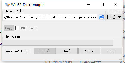
点击软件中的蓝色文件夹选择ISO镜像,在device一栏中选择内存卡盘符。确认无误后点击write写入,根据USB接口的不同,写入速度可能不同,所需的时间也不尽一样。但等待20至30分钟是必须的,毕竟镜像有4GB那么大。
写入完成后即可将其插入树莓派中,并通过HDMI连接线将树莓派与电视相互连接。然后连接USB鼠标键盘到树莓派中,还需要使用网线连接到路由器会交换机。最后连接电源线即可启动树莓派。
如果一切正常,树莓派启动的界面将会在电视中显示出来。系统无需安装,而且会直接登入到桌面中。
0x03.2 配置SSH
0x03.2.1 Root 用户
作为一个温度监测系统,我并不需要桌面环境,只需要SSH登入即可。树莓派在默认情况下,SSH服务是不启动的,这时候需要手动启用,和做一些配置。
我们要通过配置解决以下问题:
- 启用Root用户
- 修改Root用户密码
- 启用SSH密码登入
- 允许Root用户通过SSH登入
- 将SSH服务设为开机启动
因为我的树莓派已经安装到位,所以无法通过GUI界面截图。请在菜单栏中找到并打开终端,正常情况下应该是用pi这个用户登入的,所以终端中的内容如下:
pi@raspberrypi:~ $ ls
Desktop  Documents  Downloads  Music  oldconffiles  Pictures  Public  python_games  Templates  Videos
pi@raspberrypi:~ $
我们通过以下命令启用root用户并修改其密码:
#修改root用户密码
pi@raspberrypi:~ $ sudo passwd root
Enter new UNIX password:
Retype new UNIX password:
passwd: password updated successfully

#解锁root用户
pi@raspberrypi:~ $ sudo passwd --unlock root
passwd: password expiry information changed.
为了安全起见,还需要求改pi这个用户的密码:
#pi用户的默认密码为raspberry
pi@raspberrypi:~ $ passwd
Changing password for pi.
(current) UNIX password:
Enter new UNIX password:
Retype new UNIX password:
passwd: password updated successfully
0x03.2.2 SSH
启用root用户并修改密码后,通过以下命令进入root用户:
pi@raspberrypi:~ $ su
Password:
root@raspberrypi:/home/pi# cd
root@raspberrypi:~#
修改SSH的配置文件:
#打开配置文件
root@raspberrypi:~# vi /etc/ssh/sshd_config

#修改以下配置的值为yes以启用root登录
PermitRootLogin yes

#修改以下配置的值为yes并取消注释以启用密码登入
PasswordAuthentication yes
保存退出,然后通过以下命令将SSH服务设为开机启动并立即启动SSH服务:
#将SSH设为开机启动
root@raspberrypi:~# systemctl enable ssh
Synchronizing state for ssh.service with sysvinit using update-rc.d...
Executing /usr/sbin/update-rc.d ssh defaults
Executing /usr/sbin/update-rc.d ssh enable

#立即启动SSH服务
root@raspberrypi:~# systemctl start ssh
重启后,尝试使用SSH登入到树莓派:
[c:\~]$ ssh [email protected]


Host 'pi3-lan2.t.com' resolved to 10.1.2.78.
Connecting to 10.1.2.78:22...
Connection established.
To escape to local shell, press 'Ctrl+Alt+]'.


The programs included with the Debian GNU/Linux system are free software;
the exact distribution terms for each program are described in the
individual files in /usr/share/doc/*/copyright.

Debian GNU/Linux comes with ABSOLUTELY NO WARRANTY, to the extent
permitted by applicable law.
Last login: Sat Jun 10 13:10:44 2017 from terence-pc.t.com

SSH is enabled and the default password for the 'pi' user has not been changed.
This is a security risk - please login as the 'pi' user and type 'passwd' to set a new password.

root@raspberrypi:~#
如果一切正常,你将会看到以上内容。这时候可以将树莓派关机放到一边,继续硬件的部分。
0x04 硬件
0x04.1 GPIO
首先要先了解树莓派上的GPIO接口,树莓派26针接口如下图:

各个针所对应的功能如下图:

因为DS18B20温度传感器的工作电压在3~5.5V DC,所以我选用1号针,3.3V供电。零线选用6号针,而传输数据则需要选择黄色的GPIO针,在这里我选择3号针,也就是GPIO3。
对应关系如下:
- pin 1:直流3.3V电源
- pin 6:零线
- pin 3:数据线 GPIO3
另外我还给我的树莓派配置了一个5V的散热风扇,所以还需要在2号针接一根线到风扇中。
0x04.2 DS18B20
了解树莓派上GPIO针的功用,还需要了解DS18B20这个型号的温度传感器上三个针脚的功能。
DS18B20数字式温度传感器可以测量零下55摄氏度到零上125摄氏度,精度为正负0.5摄氏度。因为每个传感器都有独立的序列号,因此可以将多个传感器串联在一起。
外观如下:

传感器一边有圆弧,一边为平面。平面一侧印有型号等信息,我们以平面一侧为正面,针脚功用如下:
- 左侧针脚:零线
- 中间针脚:数据线
- 右侧针脚:火线
火线接3.3V直流电,数据线需要用一个4.7千欧姆的电阻与火线相连接。
0x04.3 电路
了解完硬件,要来设计电路。因为传感器可以相互串联而不会有干扰,所以我购买5个传感器,计划安装在不同位置。
简单的电路图如下:
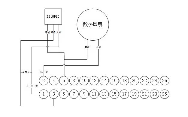
电路图知识全还给老师了,将就点看吧。
如果你有多个传感器,可以将传感器之间的针脚相互串联起来。
0x04.5 整合
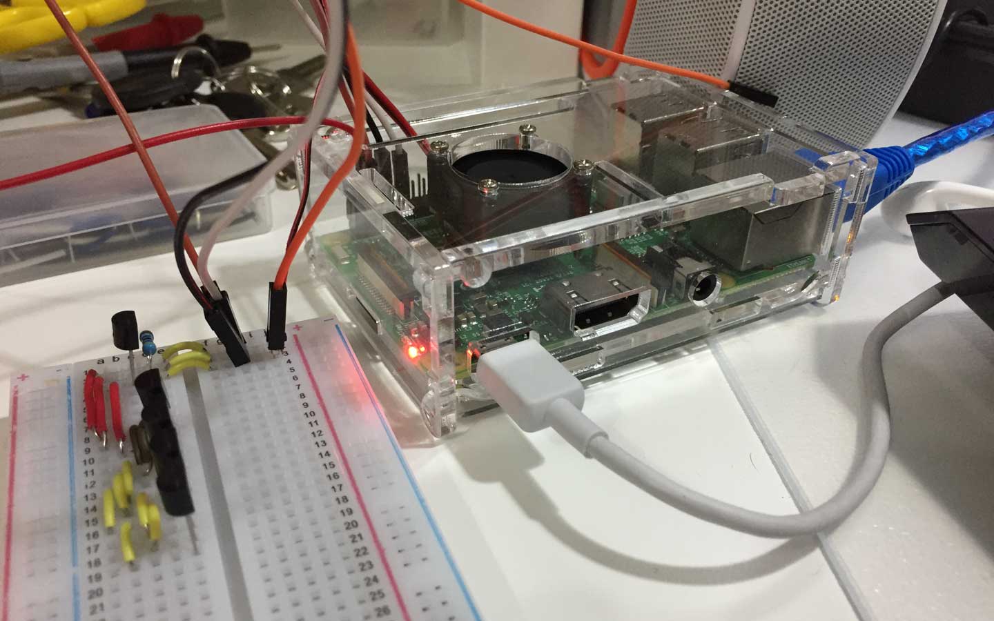
一切准备就绪就可以开始整合测试,将电路在面包板上连接好:

因为我有多个传感器,所以我将E列设为插槽,a到d列用于串联跳线。面包板准备好后先把传感器插到面包板上并连接到树莓派中进行测试:
0x05 数据
树莓派的系统准备好,确认能通过SSH登录后进行硬件配置。确认硬件也配置完成后就可以在树莓派系统中检查是否能检测到传感器的存在。
首先登入到树莓派系统中并进入以下路径:
root@raspberrypi:~# cd /sys/bus/w1/devices/
使用以下命令将目录中的文件夹罗列出来:
root@raspberrypi:/sys/bus/w1/devices# ls -l
total 0
lrwxrwxrwx 1 root root 0 Jun 10 16:10 28-0316b4cdb2ff -> ../../../devices/w1_bus_master1/28-0316b4cdb2ff
lrwxrwxrwx 1 root root 0 Jun 10 16:10 28-0316b4eb37ff -> ../../../devices/w1_bus_master1/28-0316b4eb37ff
lrwxrwxrwx 1 root root 0 Jun 10 16:10 28-0316b4f282ff -> ../../../devices/w1_bus_master1/28-0316b4f282ff
lrwxrwxrwx 1 root root 0 Jun 10 16:10 28-0316b5188aff -> ../../../devices/w1_bus_master1/28-0316b5188aff
lrwxrwxrwx 1 root root 0 Jun 10 16:10 28-0416c125c3ff -> ../../../devices/w1_bus_master1/28-0416c125c3ff
lrwxrwxrwx 1 root root 0 Jun 12 13:36 w1_bus_master1 -> ../../../devices/w1_bus_master1
可以看到我的系统中存在5个温度传感器,而且序列号都是唯一的。在各个传感器文件夹中有以下文件:
root@raspberrypi:/sys/bus/w1/devices# ls -l 28-0316b4cdb2ff/
total 0
lrwxrwxrwx 1 root root    0 Jun 12 13:37 driver -> ../../../bus/w1/drivers/w1_slave_driver
-r--r--r-- 1 root root 4096 Jun 12 13:37 id
-r--r--r-- 1 root root 4096 Jun 12 13:37 name
drwxr-xr-x 2 root root    0 Jun 12 13:37 power
lrwxrwxrwx 1 root root    0 Jun 12 13:37 subsystem -> ../../../bus/w1
-rw-r--r-- 1 root root 4096 Jun 10 16:10 uevent
-rw-r--r-- 1 root root 4096 Jun 10 16:10 w1_slave
其中w1_slave这个文件记录着传感器当前的值,我们可以使用cat这个命令打印到终端:
root@raspberrypi:/sys/bus/w1/devices# cat 28-*/w1_slave
06 02 4b 46 7f ff 0c 10 21 : crc=21 YES
06 02 4b 46 7f ff 0c 10 21 t=32375
b7 02 4b 46 7f ff 0c 10 0c : crc=0c YES
b7 02 4b 46 7f ff 0c 10 0c t=43437
8e 02 4b 46 7f ff 0c 10 99 : crc=99 YES
8e 02 4b 46 7f ff 0c 10 99 t=40875
8d 02 4b 46 7f ff 0c 10 5c : crc=5c YES
8d 02 4b 46 7f ff 0c 10 5c t=40812
02 02 4b 46 7f ff 0c 10 34 : crc=34 YES
02 02 4b 46 7f ff 0c 10 34 t=32125
在输出的内容中,t的值就是温度值。我们只需要温度值除以1000就是当前探测到的温度。
如果你也能获取到输出的数值,证明一切正常,可以继续下一步。
0x06 zabbix
可以成功获取数值已经是成功了一大半,我还希望实现取值自动化,还需要实现报警功能。当温度过高,可以给我发送邮件等通知。
在这里我使用zabbix实现取值、分析和报警等功能。
0x06.1 shell
首先我们需要写个脚本,让zabbix agent使用。因为传感器的序列号都是固定唯一的,而且w1_slave这个文件中的内容格式都一样,所以我使用以下命令截取数值:
tail -n 1 /sys/bus/w1/devices/28-$*/w1_slave | cut -d = -f 2
将上面命令写入到文件中并命名为:pi3-temp-sensor.sh
root@raspberrypi:/sys/bus/w1/devices# cat /usr/local/shell/pi3-temp-sensor.sh
tail -n 1 /sys/bus/w1/devices/28-$*/w1_slave | cut -d = -f 2
我们选取一个传感器序列号测试以上脚本:
root@raspberrypi:/sys/bus/w1/devices# sh /usr/local/shell/pi3-temp-sensor.sh 0316b4cdb2ff
32437
root@raspberrypi:/sys/bus/w1/devices# sh /usr/local/shell/pi3-temp-sensor.sh 0316b4eb37ff
43187
当我向脚本传入传感器序列号后,可以返还正确的数值。
0x06.2 zabbix agent
有了shell,我们还需要为zabbix agent写一个自定义函数,以便在zabbix server中调用。首先安装zabbix agent:
root@raspberrypi:/sys/bus/w1/devices# apt-get install zabbix-agent
Reading package lists... Done
Building dependency tree
Reading state information... Done
zabbix-agent is already the newest version.
0 upgraded, 0 newly installed, 0 to remove and 0 not upgraded.
然后进入zabbix agent配置文件夹:
root@raspberrypi:/sys/bus/w1/devices# cd /etc/zabbix/zabbix_agentd.conf.d/
在该文件夹中新建一个配置文件并填入内容:
root@raspberrypi:/etc/zabbix/zabbix_agentd.conf.d# cat pi3-temp-sensor.conf
UserParameter=pi3-temp-sensor.sensor1,sh /usr/local/shell/pi3-temp-sensor.sh 0316b4eb37ff
UserParameter=pi3-temp-sensor.sensor2,sh /usr/local/shell/pi3-temp-sensor.sh 0316b4cdb2ff
UserParameter=pi3-temp-sensor.sensor3,sh /usr/local/shell/pi3-temp-sensor.sh 0416c125c3ff
UserParameter=pi3-temp-sensor.sensor4,sh /usr/local/shell/pi3-temp-sensor.sh 0316b5188aff
UserParameter=pi3-temp-sensor.sensor5,sh /usr/local/shell/pi3-temp-sensor.sh 0316b4f282ff
我在这个文件夹中新建了名为pi3-temp-sensor.conf的文件并填入我自定义的函数。
该函数中含有一个逗号“,”逗号左侧为自定义的key,可自定义;右侧为shell命令。
完成后启动zabbix agent:
#立即启动zabbix agent
root@raspberrypi:/etc/zabbix/zabbix_agentd.conf.d# systemctl start zabbix-agent

#将zabbix agent设为开机启动
root@raspberrypi:/etc/zabbix/zabbix_agentd.conf.d# systemctl enable zabbix-agent
Synchronizing state for zabbix-agent.service with sysvinit using update-rc.d...
Executing /usr/sbin/update-rc.d zabbix-agent defaults
Executing /usr/sbin/update-rc.d zabbix-agent enable
如果需要了解zabbix agent更多内容,请浏览以下文章:
配置完成后还需要在zabbix server中测试自定义函数是否有效。先到zabbix server系统中找到zabbix_get命令,因为我的zabbix server是自行编译的,如果有需要,可以参考以下文章:
使用zabbix_get命令检查自定义函数是否有效:
[root@web ~]# /usr/local/zabbix/bin/zabbix_get -s pi3-lan2.t.com -k pi3-temp-sensor.sensor1
43375
[root@web ~]# /usr/local/zabbix/bin/zabbix_get -s pi3-lan2.t.com -k pi3-temp-sensor.sensor2
32562
[root@web ~]# /usr/local/zabbix/bin/zabbix_get -s pi3-lan2.t.com -k pi3-temp-sensor.sensor3
31625
[root@web ~]# /usr/local/zabbix/bin/zabbix_get -s pi3-lan2.t.com -k pi3-temp-sensor.sensor4
42312
[root@web ~]# /usr/local/zabbix/bin/zabbix_get -s pi3-lan2.t.com -k pi3-temp-sensor.sensor5
42625
如果你的配置正确无误,那终端中返还的内容应该和我的一致。
0x06.3 zabbix server
最后是在zabbix server中添加模板和监控点。
0x06.3.1 模板
在zabbix控制面板中找到configuration–>template,新建一个模板:
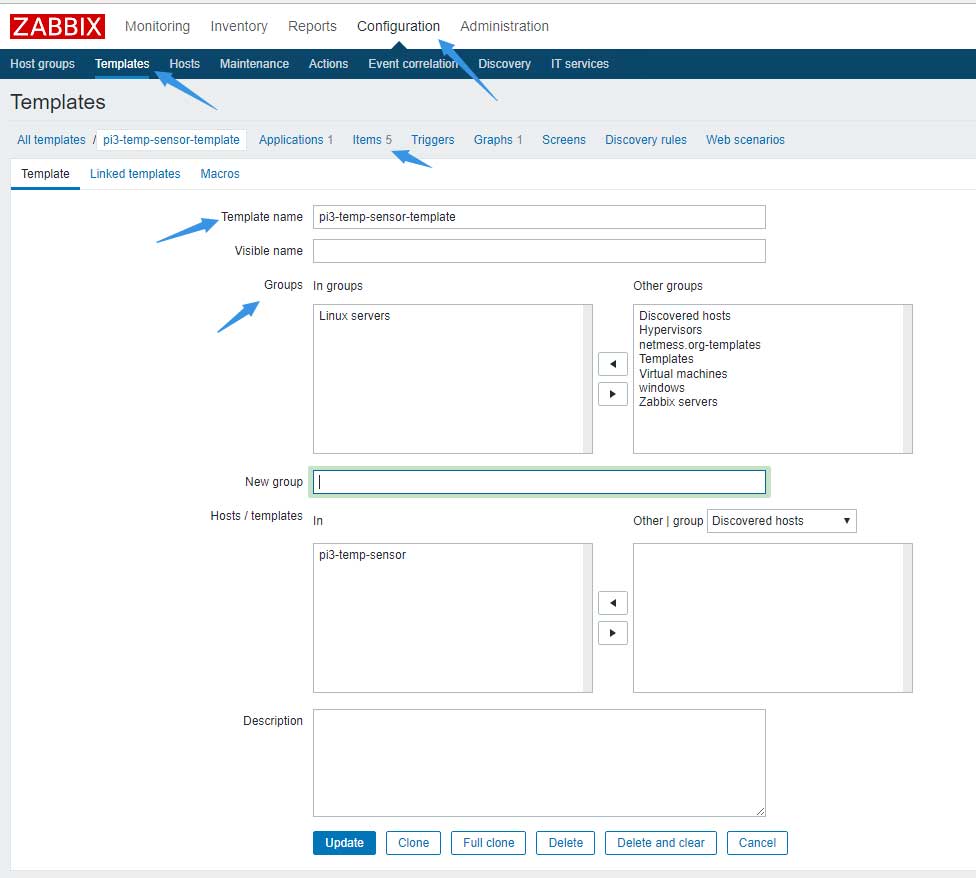
填入模板名称,选择群组后点击items,并新建item:
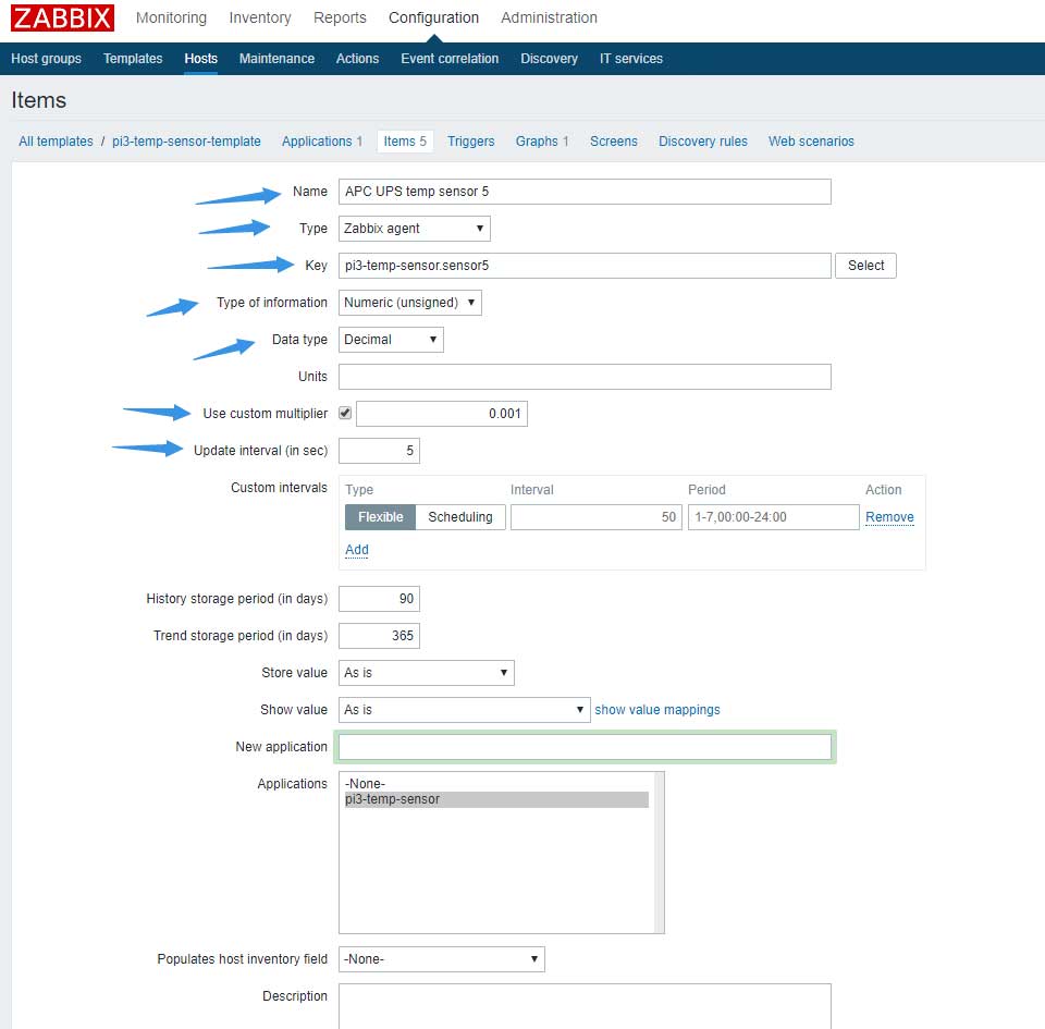
根据以下提示填写内容:
- Name:item名称
- type:选择zabbix agent
- key:自定义函数
- type of information:选择Numeric,数字类型
- Use custom multiplier:勾选并填写0.001,意为除以1000
- Update interval (in sec):取值间隔,我设为5秒
确认无误后保存并继续添加其他传感器。如果需要更多相关信息,请参考以下文章:
0x07 结语
因为我是初次接触电子,但很庆幸没有走弯路。传感器没有延长线,所以我用网线作为延长线,用焊锡焊在一起。淘宝上还有一种是焊好的,外观比较好看:

而自己动手焊接更有乐趣,只是外观比较难看:


0x08 相关视频
https://www.bilibili.com/video/av11233301/
- YouTube:EP11 – 基于树莓派的温度监控系统与zabbix简单配置


服务器散热风扇的转速")


